Normally I use a keyboard and a screen connected to a new Raspberry Pi for doing the initial setup. Once the network and SSH are up and running, I connect from remote to do the rest of the setup.
As an alternative I tried to establish a connection between the Raspberry Pi (in this particular case a Raspberry Pi 3 Model B) and a laptop using a TTL to USB converter. Of course it works - but there are some things you need to know besides the general things described on Wikipedia. The summary provided here might help others struggling with similar problems.
This post shows only my personal experiences with the specific hardware I used. For this reason I cannot accept any responsibility or liability in case anything is damaged.
Wire things together
First of all things need to be wired together, because my converter consists of the USB part offering some pins and five cables in different colors.
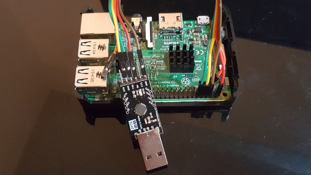
The USB part shows some labels for each pin. After reading some other posts (this one was helpful) I found out which pin of the Raspberry Pi fits to which one on the USB side. The image above shows the result. It worked although I’m not sure if I chose the right colors. But that’s not that important if the right pins are connected to each other.
The table below is based on the image. For a better understanding of the pin numbering on the Raspberry Pi side you can have a look at this description or the GPIO pin picture in this tutorial. One important thing is to connect TXD with RXD and RXD with TXD, because those are the pins for sending (TXD) and receiving data (RXD). A sending pin needs to be connected to a receiving pin.
| Color | Raspberry Pi | USB |
|---|---|---|
| Red | 5V (Pin 2) | 5V |
| Brown | GND (Pin 6) | GND |
| Yellow | TXD (Pin 8) | RXD |
| Green | RXD (Pin 10) | TXD |
Please be careful. If you connect the 5V pin, you must not plug in the external power supply of the Raspberry Pi. It will get the power via the red cable.
Access the debug console
After the pins are connected, it’s time to test the connection to the debug console. To do this, you need to plug in the USB part into your laptop. I used Windows 10 and didn’t need to install any additional drivers - but this might be the case on other platforms.
Once the converter is recognized and registered as serial device, e.g. Putty can be used for connecting to the debug console. The screenshot below shows the connection settings I needed to use.
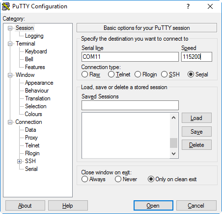
The COM port might differ but you should make sure to choose the right speed resp. the correct baud rate. If the connection is established but weird characters are shown in the console window, the baud rate might be wrong.
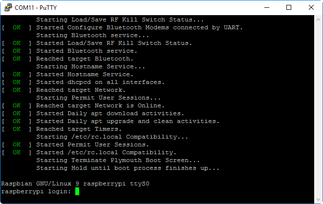
Once the connection was established successfully you should see the same output like you would see on a screen directly connected to the Raspberry Pi.
Leave A Comment
I'd love to hear your opinion and experiences. Share your thoughts with a comment below! Please note that comments will appear after moderation.